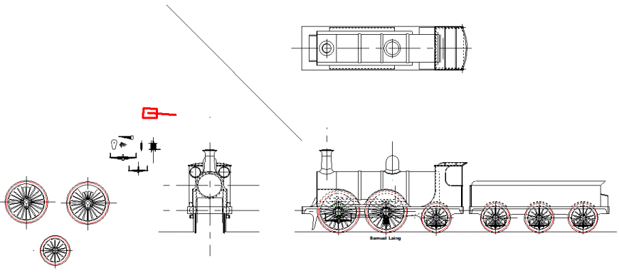
Sheet1 General Arrangement (Version 008)
Drawing Sheet
Notes
Today's effort was the completion of the tender outline. No major thinking required, but on completion and checking with the photographs, I realise that the detail of the tender body, where the cab steps will appear, is actually not quite right. It seems that when viewed from above this corner of the tender body has a big radius, like the rear. The vertical handrail is actually secured at the top by a large flat protrusion from the tender body, in that curve.
What I drew was a flat side coming to a square edge. This is why the secondary lower handrail is not shown. It too, is positioned on that curve.
The top view of the tender has been left for the time being, because I simply have no pictures of the top of the locomotive. Most of the top of the engine can be inferred from pictures, and the side elevations. This is not true for the tender. This detail will have to wait for my visit to the real locomotive at York.
The cab steps have not yet been drawn. I think I know how they are supposed to be from the side elevation line drawings I already have, and the pictures. What's in my mind doesn't somehow seem right, so I'm leaving those too for my visit to the NRM at York.
The tender frame outline was relatively straightforward to draw. The lines of the frame are similar to the locomotive. Fortunately there are no significant strength issues with the tender frames. Perhaps the detail drawings will show a couple of rod stretchers between the frames. The base of the tender body provides ample rigidity in the tender. If I implement a tender axle pump a more substantial stretcher will be used to mount it. The arrangement of wheels and axleboxes is the same as that of the trailing wheels on the locomotive. This latter feature is one which I think makes the locomotive look particularly smart. |


